Precise localised temperature control by varying the rate of airflow.
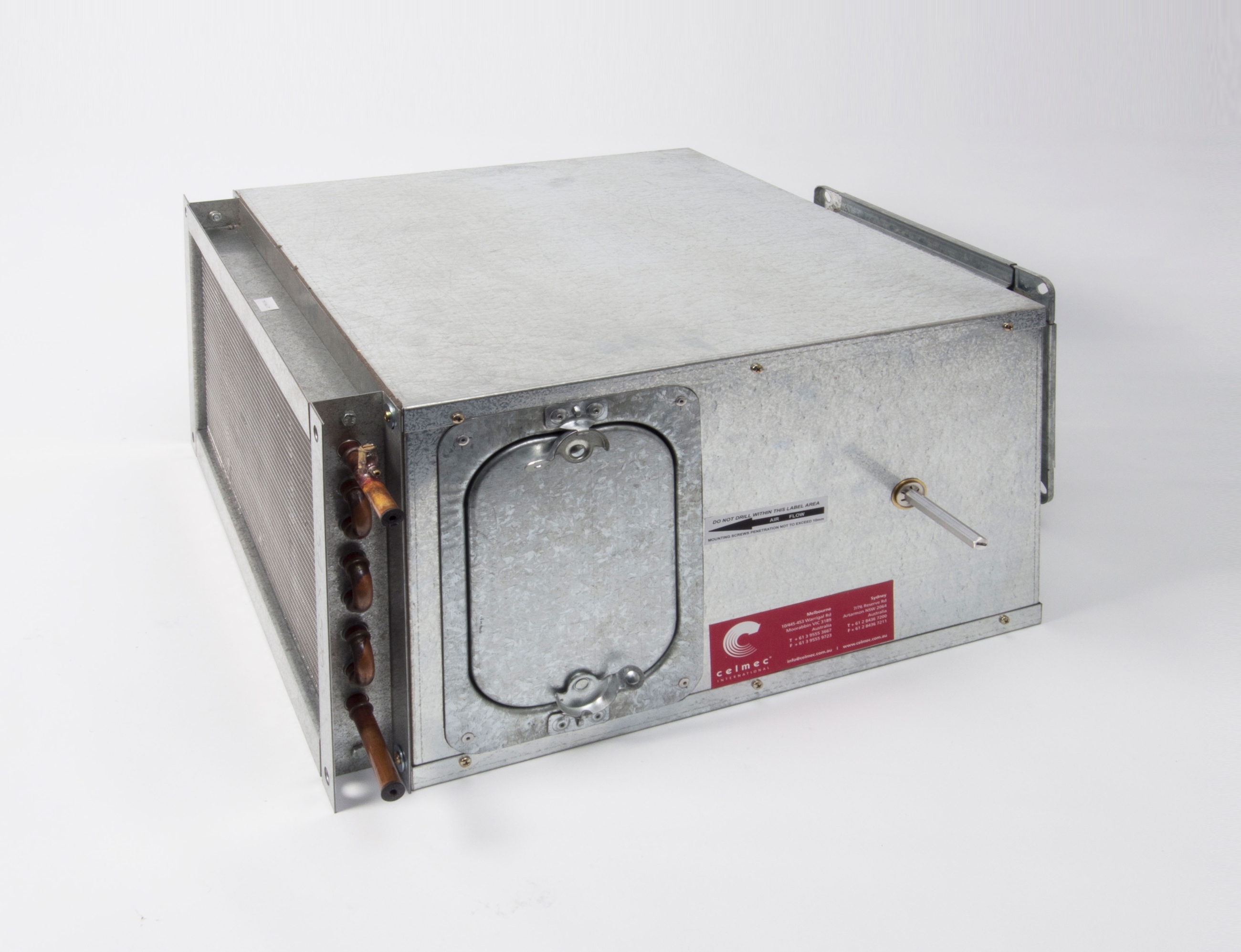
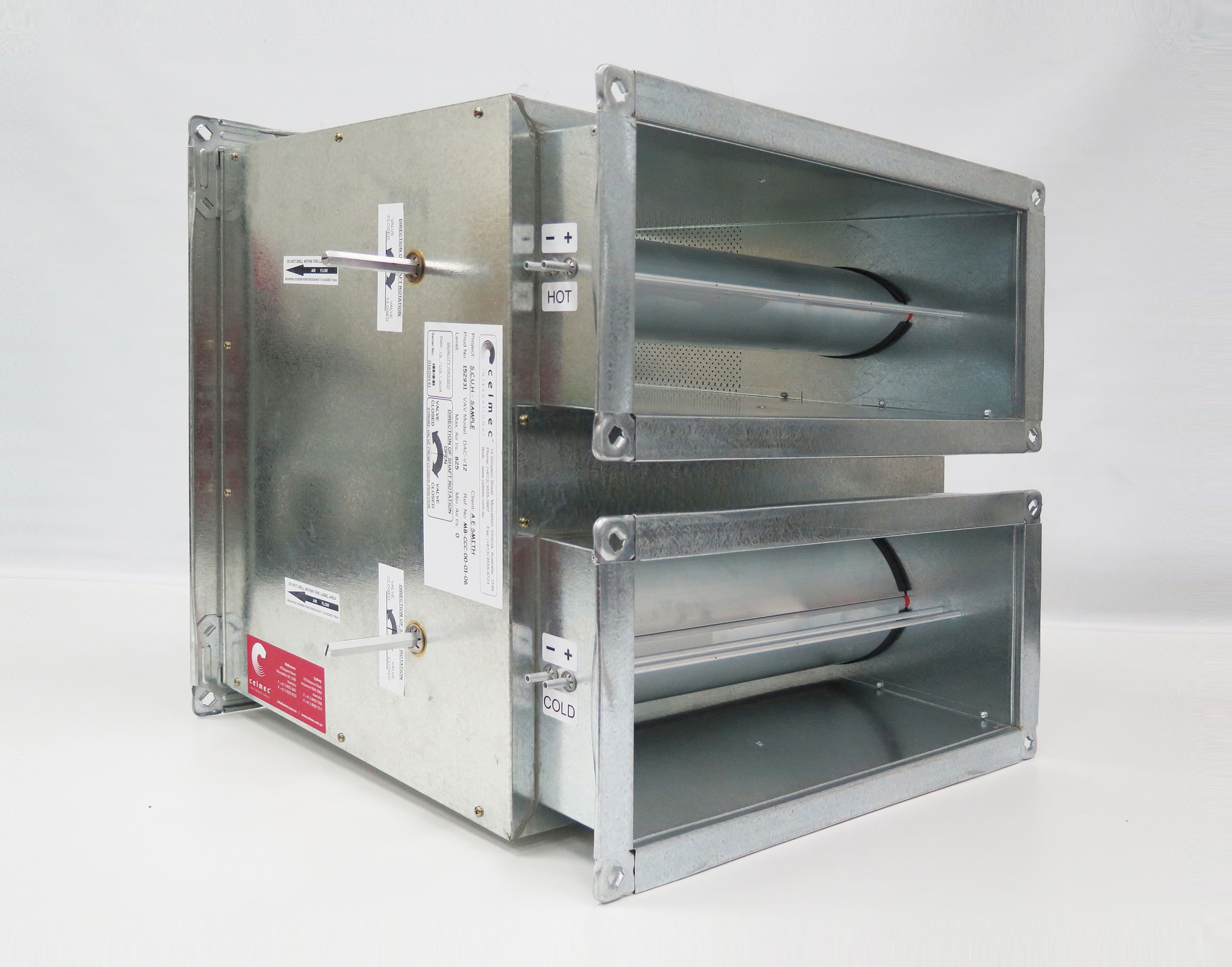
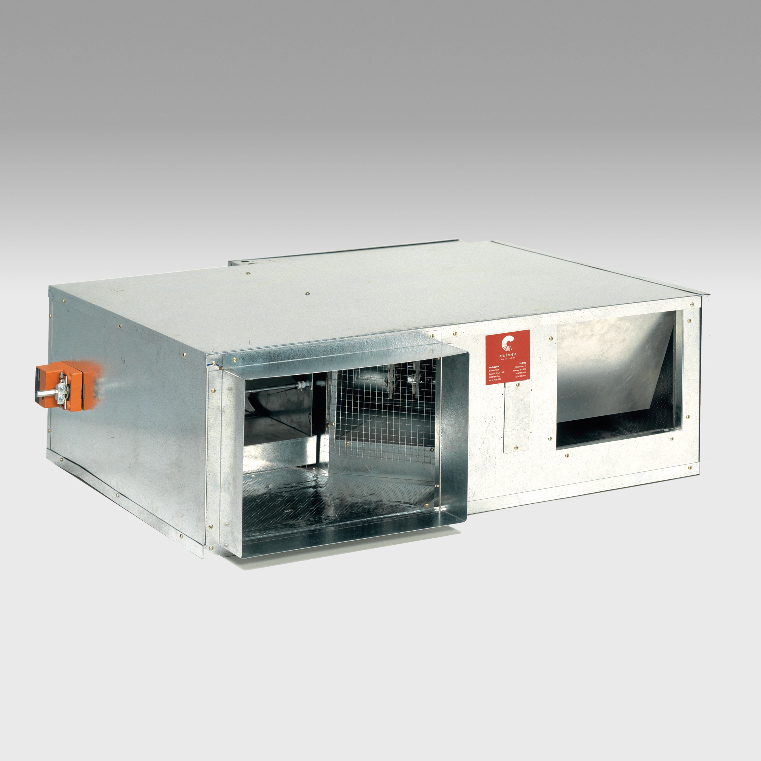
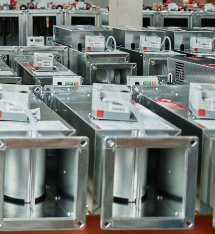
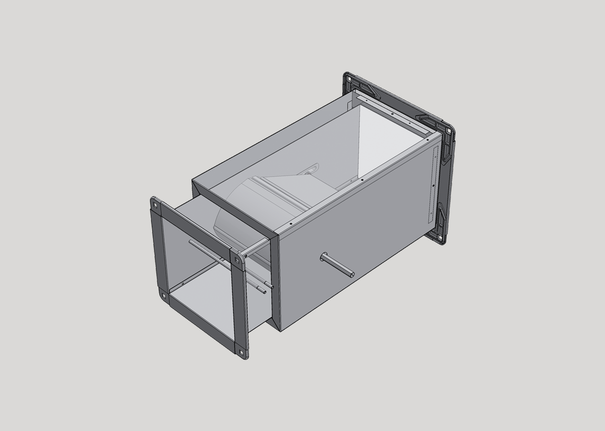
 At the heart of our VAV Terminal Units is our pioneering and patented Aerofoil Control Valve, which provides industry leading performance any way you look at it. Built locally inhouse to our exacting standards and specific material tolerances, with or without electric or hot water heating, fan assisted in parallel or series, dual and twin duct options.
-
Linear Control
Accurate air flow control, configured to have a linear flow/stroke relationship.
-
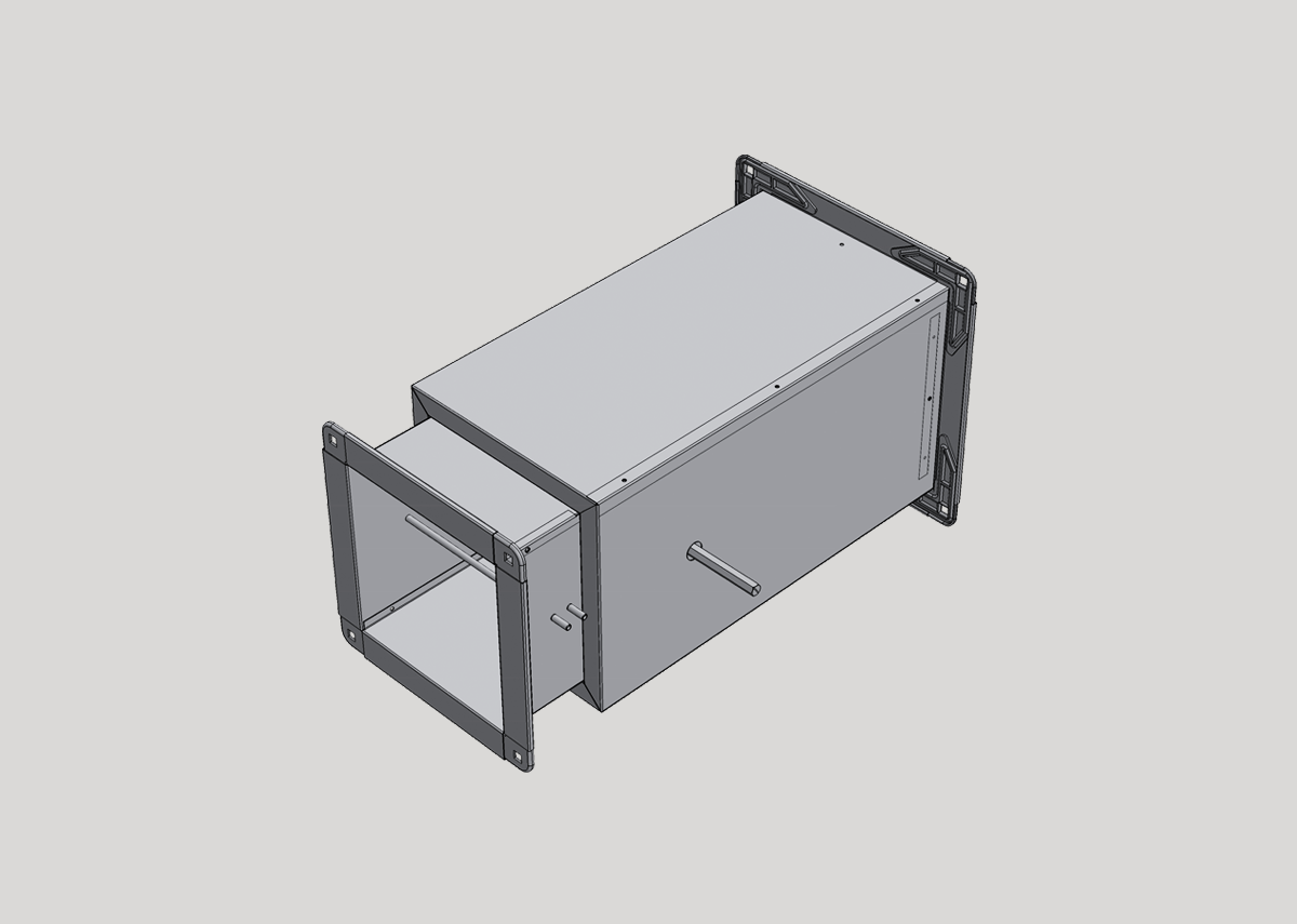
Acoustic Performance
Significantly reduced radiated and low frequency noise levels compared to conventional systems.
-
Energy Efficiency
The Aerofoil Valve produces laminar air flow patterns, ensuring even air distribution across heating coils, minimising hot spots and air resistance for maximum efficiency.
-
Low Toxicity & Chemical Free
25mm and 50mm thick high-density poly fibre insulation. Made from 80% recycled polyester fibre. Non-allergenic and free from harmful particles, chemicals and resins.
-
Tropical VAV’s
‘No sweat’ construction eliminates metal to metal contact to combat surface condensation and potential water damage in highly humid conditions.
-
Hospital VAV’s
Custom built and fully lined internally to completely isolate the airflow from contact with the insulation to prevent bacterial accumulation or transfer.
- Airflow range 25LPS-1800LPS.

- Airflow range 30LPS-1800LPS.
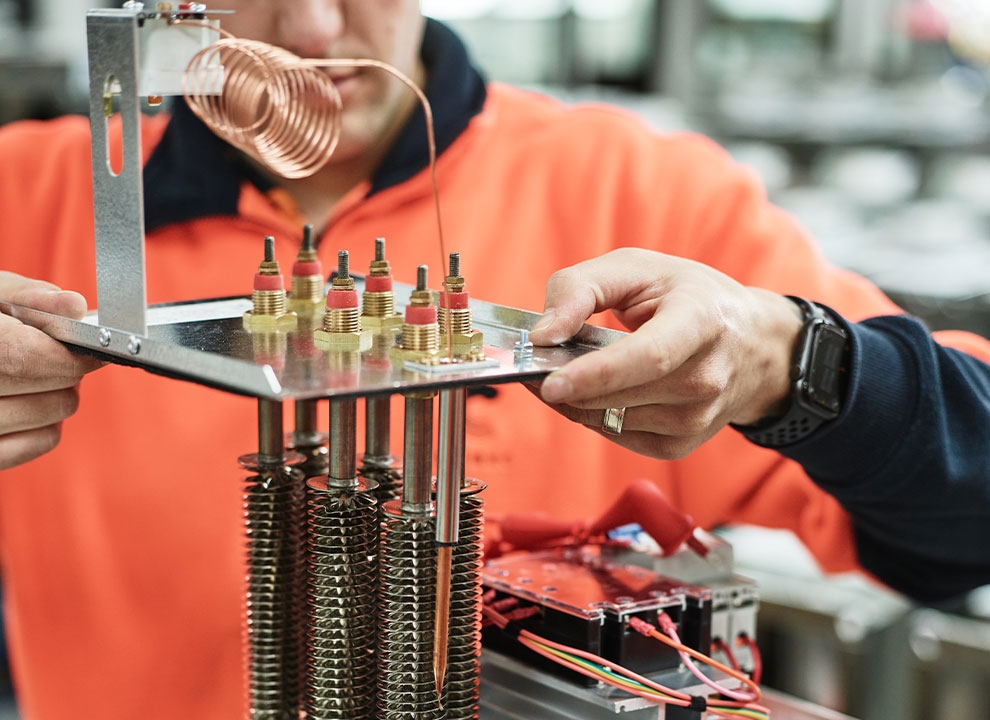
- Heating range 0.25kW-10.05kW.

- Airflow range 25LPS-1450LPS.
- Heating range 1kW-14kW.
- Airflow range 100LPS-1400LPS.
- Airflow range 100LPS-1400LPS.
- Heating range 0.25kW-5kW.
- Airflow range 100LPS-1100LPS.
- Heating range 1kW-10kW.


- Airflow range 100LPS-1250LPS.

- Airflow range 100LPS-1250LPS.
- Heating range 0.25kW-5kW.

- Airflow range 100LPS-1100LPS.
- Heating range 1kW-10kW.

- Airflow range 50LPS-1600LPS.
- Airflow range 50LPS-2200 LPS.


- Airflow range 50LPS-250LPS.